| TRM6x4 or TRM44 |
Compact headend |
| Quad DVBS/S2 to DVBT transmodulator | |
| – | |
 |
Main system features: |
| Transmodulator DVBS/S2 to DVBT with four satellite inputs | |
| – | |
| The programs of the four satellite inputs can be distributed over the four | |
| adjacent DVBT output channels |
|
| Remultiplexers are inside, so that program to channel assignment can | |
| be freely chosen | |
| Mini DTVRack composed of 2 x DTVRR5 and 1 x DTVDM2, with integrated | |
| power supply | |
| Additionally it has the unique feature that it allows to create your own | |
| program(s) | |
| TS files (containing a video or information) present on a USB stick can be | |
| used to create your ‘own’ content/program. The name of the program can |
|
| be freely chosen | |
| Finally this program can be added to one of the output DVBT channels. | |
| A programmable timetable, allows to distribute different .ts files during the day |
|
| In addition RJ45 connectivity allows the transmodulator to be connected to | |
| the internet | |
| In such way, remote control/access over the web is possible | |
| Also, contents available on the USB stick(s) to create your own channel | |
| can be changed remotely | |
| A large number of applications in the residential or commercial sector for | |
| distributing satellite programs over a DVBT network (hotels, hospitals and | |
| so on) and to distribute additional information (videos / text messages etc.) |
|
| Easy programmable using the program DTVIface | |
| Small dimensions and esthetic design | |
 |
|
| HEADEND | |
| CMH3000 | |
 |
Compact modular headend CMH3000 |
| Main system features: | |
| All parameters of the modules are controlled by programming via CMH data bus | |
| Local or remote control/monitoring system using PC | |
| Extended self-diagnostic | |
| Open architecture system for easy integration of new components | |
| Headend powering redundancy | |
| Possibility of hot installing/replacing modules | |
 |
Possibility to “clone” headend’s settings from the saved configuration file |
| – | |
| The technical platform: | |
| The basic unit of CMH3000 headend is 19” width 6U subrack | |
| One subrack has 8 identical slots for 8 modules. Data and DC distributing, RF combining and | |
| RF input signal feeding of each module is realized through passive bus bar | |
| Input RF signal distribution panel and rear mount output amplifier can be installed optionally | |
| – | |
| Up to 16 subracks can be connected to single USB port of PC. Hand held control |
|
| unit can also be used for programming up to 16 modules in 2 subracks |
|
| (connection on the front panel of power supply unit) | |
 |
UC180 – Base unit |
| 6U height 19” width subrack for up to 8 modules installation; & data distribution bus and output | |
| RF combiner | |
| Input distribution blocks DP180, DP181 and rear mount output amplifier can be integrated | |
| optionally | |
| DC and data bus extension ports | |
| Possibility to supply DC from centralized PS | |
| Two base units could be interconnected for redundancy by DC powering | |
| Built-in switcher for setting of virtual address | |
| |
|
 |
CT120B – Twin TV channel converter, standard B/G/I |
| Input adjacent channel to output adjacent channel converter of analogue TV programs | |
| Works via low frequency IF and allows to change program’s retransmitting frequency | |
| – | |
| Double SAW filtering on IF | |
| High selectivity determinated by SAW filter | |
| AGC system at input | |
| Low level harmonics and intermodulation products | |
| 12V DC for preamplifier powering | |
| – | |
| RF input, frequency range: 47- 68 MHz, 174-230 MHz, 470-862 MHz | |
| RF output, frequency range: 47-862 MHz | |
| RF output, level/impedance: 98 dBμV/75 Ω | |
| Output level adjustment range: 0 ÷ -10 dB by 0.5 dB step | |
 |
UP100 – Power supply |
| Provides the powering voltage for all components of CMH3000 system | |
| This is high efficiency unit with short circuit and overload protection | |
| – | |
| Switch-mode technology | |
| Socket for handheld control unit connection PC100 | |
| Suitable for operation in parallel connection for back-up function implementation | |
| Measurement of output level and current | |
| Indication: | |
| Over temperature | |
| Overload | |
| – | |
| Input voltage: 187-250 V~ 50 Hz | |
| Output voltage, current: 24 V 9 A max | |
| Power consumption: 245 W max | |
 |
UA200R30 – Output amplifier |
| Amplifying RF signal incoming from one or two base units UC180 | |
| – | |
| 2 inputs high output level system amplifier | |
| Measurement of output level and current internal consumption | |
| Integrated switch for redundancy | |
| Test points of forward and return channels | |
| – | |
| Frequency range, forward path: 47-862 MHz | |
| Frequency range, return path: 5-30 MHz | |
| Gain: 24 dB – 2 inputs, 28 dB – 1 input | |
| Output level CTB (-60 dB, EN50083-3): 111 dBμV | |
| Output level CSO (-60 dB, EN50083-3): 112 dBμV | |
| Slope adjustment: 10 dB by 0.5 dB step | |
| Gain adjustment: 10 dB by 0.5 dB step | |
| Test point attenuation: -20 dB max. (± 0.75 dB) | |
| Current consumption: 0.65 A | |
| |
|
| MMH3000 | |
 |
Mini modular headend MMH3000 |
| Main system features: | |
| Mini modular headend MMH3000 is compact solution for the distribution of DVB-S and DVB-T | |
| signals for SMATV and CATV networks | |
| The modern master-slave technology allows to build cost-effective installations and simplify a | |
| circuitry of SAT IF and terrestrial input signal distribution | |
| |
Programming of MMH3000 could be made locally by handheld programmer and software or |
 |
remotely through internet or other communication line using advanced |
| control and monitoring software. Also is possible to “clone” headend’s settings from the saved | |
| configuration file | |
| Almost all parameters of the modules are controlled by programming via CMH data bus | |
| It is necessary minimal amount of additional external equipments for installation of the headend | |
| – | |
| Mini modular headend MMH3000 consists of: | |
| Base units for 8 modules installation | |
| DVB-S channels modules | |
| DVB-T channels modules | |
| TV modulators | |
| TV converter modules | |
| MPEG2 TS decoders-modulators | |
| Handheld control unit | |
| Control software and appropriate interfaces | |
| |
|
 |
UC380 – Base unit |
| Base unit for up 8 modules installation | |
| Wall or 19” rack 5U height mounting | |
| Built-in power supply, RF output amplifier with combiner, power and data distribution bus | |
| Data bus extension ports | |
| All external connections from top and bottom sides | |
| Integrated fan | |
| |
|
|
|
CT310 – Analog and digital TV channel converters |
| Input channel to output channel converter | |
| Works via low frequency IF and allows to change program’s retransmitting frequency | |
| – | |
| Double conversation technology | |
| High selectivity determinated by double SAW filters | |
| AGC system at input | |
| Input signal level and P/S carriers ratio measurement | |
| Low level harmonics and intermodulation products | |
| 12V DC for preamplifier powering | |
| Input RF loop through | |
| – | |
| RF input frequency range: 45-862 MHz | |
| RF input level/impedance: 60-90 dBμV/75 Ω | |
| RF input loop through frequency range: 47-862 MHz | |
| RF output frequency range: 110-862 MHz | |
| RF output level/impedance: 100 dBμV/75 Ω | |
| |
|
 |
RD315C – 8PSK/QPSK-PAL/SECAM receiver with |
| VSB modulator, standard B/G/D/K/stereo A2 | |
| For receiving of DVB-S/S2 SAT IF signals and converting it to analogue TV programs | |
| Works as “master” module for distribution MPEG2 transport stream to “slave” modules | |
| Input signal level measurement | |
| Built-in CA interface (option) | |
| Input signal level measurement | |
| Teletext reinsertion & DVB subtitles decoding | |
| Software/hardware watchdog timer | |
| Low level harmonics and intermodulation products | |
| Input RF loop through | |
|
– |
|
| Connectors: | |
| MPEG2 TS output | |
| RF input & output – type F | |
| – | |
| Receiver: | |
| RF input frequency range: 950 -2150 MHz | |
| RF input level/impedance: 30-88 dBμV/75 Ω | |
| Input data symbol rate: 1÷ 45 MS/s | |
| MPEG2 TS output: 2 ÷ 80 Mbit/s | |
| – | |
| Modulator: | |
| RF output level/impedance: 100 dBμV /75 Ω | |
| RF output frequency range: 110-862 MHz | |
| RF output level adjustment range: 0 ÷ -15 dB | |
| |
|
 |
RT316 – OFDM-PAL/SECAM receiver with |
| DSB modulator standard B/G/D/K/I/L/M/N | |
| For receiving of DVB-T MPEG-2/MPEG-4/H.264 coded terrestrial TV signals and | |
| converting it to analogue PAL or SECAM TV programs | |
| Works as “master” module for distribution MPEG2 transport stream to “slave” modules | |
| Input signal level measurement | |
| Built-in CA interface (option) | |
| BISS descrambling | |
| Teletext reinsertion & DVB and teletext subtitles decoding | |
| Software/hardware watchdog timer | |
| Low level harmonics and intermodulation products | |
|
– |
|
| Connectors: | |
| MPEG2 TS output | |
| RF input & output – type F | |
| – | |
| Receiver: | |
| RF input frequency range: 174-230 MHz, 470 -862 MHz | |
| RF input level/impedance: 30-88 dBμV/75 Ω | |
| Preamplifier powering: 0/12 V 100 mA max | |
| MPEG2 TS output: 2 ÷ 32 Mbit/s | |
| – | |
| Modulator: | |
| RF output level/impedance: 100 dBμV /75 Ω | |
| RF output frequency range: 119-300 MHz & 470-862 MHz | |
| RF output level adjustment range: 0 ÷ -15 dB | |
| MT310 – TV modulator | |
| Modulating analogue video/audio signals into VSB RF channel with mono or stereo A2 sound | |
| – | |
| Output level stabilization | |
| Carriers crystal stabilization | |
| Low level harmonics and intermodulation products | |
| – | |
| Connectors: | |
| Video/audio, input – 15 Sub-D socket | |
| – | |
| Frequency range: 110-862 MHz | |
| RF output, level/impedance: 100 dBμV/75 Ω | |
| Output level adjustment range: 0 ÷ -10 dB | |
| – | |
| |
|
 |
TDX311 – 8PSK/QPSK-COFDM transmodulator |
| Converting of DVB-S/S2 8PSK/QPSK modulated SAT IF signal into | |
| COFDM/QAM modulated DVB-T RF channel | |
| TS processing: | |
| EPG multiplexing | |
| PCR restamping | |
| Service filtering | |
| PSI/SI regeneration | |
| NIT generation | |
| PMT version monitoring | |
| – | |
| Connectors: | |
| MPEG2 TS output | |
| RF input & output – type F | |
| – | |
| Receiver: | |
| RF input frequency range: 950 -2150 MHz | |
| RF input level/impedance: 45-85 dBμV/75 Ω | |
| RF input modulation: QPSK, 8PSK (DVB-S/S2) | |
| RF input symbol rate: 1÷ 45 MS/s | |
| RF input LNB powering/control: 0/18 V 400 mA max | |
| RF input loop through frequency range/gain: 950-2150 MHz/2 dB | |
| MPEG2 TS output: 2 ÷ 31.66 Mbit/s | |
| – | |
| Modulator: | |
| RF output level/impedance: 90 dBμV/75 Ω | |
| RF output frequency range: 110 – 860 MHz | |
| RF output level adjustment range: 0 ÷ -15.5 dB by 0.5 dB step | |
| RF output C/N: ≥ 50 dB | |
| RF output MER: ≥ 35 dB | |
| RF output modulation: QPSK, QAM16, QAM64 | |
| RF output channel bandwidth: 7/8 MHz | |
| RF output guard interval: 1/4, 1/8, 1/16, 1/32 | |
| RF output code rate: 1/2, 2/3, 3/4, 5/6, 7/8 | |
| RF output transmission mode: 2K | |
|
|
MD330 – 3-channel MPEG2 encoder |
| Channel processing equipment | |
| Converting analogue video/audio signals into MPEG2 coded transport stream | |
| – | |
| Three composite video and three stereo audio inputs | |
| Three individual MPEG2 TS outputs | |
|
MPEG2 TS PID control |
|
| Video brightness, contrast, saturation, hue control | |
| Programmable audio and video compression bit rates | |
| Programmable audio sampling rate | |
| Audio level control | |
| Parameters control via CMH data bus extension port | |
| Firmware upgradeable | |
| Connectors: 3-channel video/audio input – 15-pin Sub-D socket on the bottom side three MPEG2 | |
| TS outputs: TS1, TS2 and TS3 on the front panel | |
| – | |
| Sections: 3 | |
| Video: | |
| – encoding ISO/IEC13818-2 MPEG-2 MP@ML | |
| – resolution: 720 x 576 (at 25 fps), 720 x 480 (at 30 fps) | |
| – frame rate: 25 max. PAL, 30 max. NTSC | |
| Audio: | |
| – encoding: ISO /IEC11172-3 (MPEG1 audio) layer 1/2 compliant | |
| – sampling rate: 32 kHz, 44.1 kHz, 48 kHz | |
| – compressed bit rate: 32 to 384 Kbps per channel | |
| – audio mode: Stereo, Joint Stereo, Dual Channel, Mono | |
| Audio/Video multiplexing: ISO/IEC13818-1 MPEG2 TS | |
| Compressed system bit rate: 1 to 15 Mbps per channel | |
| Compressed system bit rate mode: constant, variable | |
| |
|

|
TRX360 – DVB-T modulators |
| Channel processing equipment | |
| Multiplexing up to 6 transport streams and converting into COFDM/QAM modulated DVB-T RF | |
| channel | |
| – | |
| TS processing: | |
| – EPG multiplexing | |
| – PCR restamping | |
| – service filtering | |
| – PSI/SI regeneration | |
| – NIT generation | |
| Connectors: | |
| – 6xMPEG TS inputs | |
| – MPEG2 TS output (multiplexed) | |
| – | |
| TS input type: serial | |
| TS input channels: 6 | |
| TS output type: serial | |
| TS input bit rate: < 100 Mbit/s | |
| TS output bit rate: < 31 Mbit/s | |
| – | |
| RF output: | |
| – frequency range: 110 – 860 MHz | |
| – level/impedance: 90 dBμV/75 Ω | |
| – output C/N: ≥ 50 dB | |
| – MER: ≥ 35 dB | |
| – modulation: QAM16, QAM32, QAM64 | |
| – guard interval: 1/4, 1/8, 1/16, 1/32 | |
| – code rate: 1/2, 2/3, 3/4, 5/6, 7/8 | |
| – transmission mode: 2K | |
| – output level adjustment range: 0 ÷ -15.5 dB by 0.5 dB step | |
| Multichannel headend 4XX series | |
 |
sda410C – DVB-S/S2 to IP and ASI |
| Modular reception system, DVB to IP streamers | |
| IP streaming and ASI output of free-to-air or descrambled DVB services | |
| – | |
| One channel IP streamers | |
| ● common interface | |
| ● one SAT transponder (descrambled or FTA) | |
| ● BISS descrambling | |
| ● SPTS or MPTS IP stream | |
| ● regeneration of information contained in the MPEG-2 tables | |
| ● UDP and RTP transmission protocols | |
| ● SDP/SAP protocol support | |
| ● Web control and SNMP agent | |
| ● loop through RF distributing | |
| ● DIN rail or wall mounting | |
| ● robust die-cast housing | |
| ● connectors: | |
| RF inputs, ASI input/output – type F | |
| Ethernet control, Ethernet stream output – RJ-45 | |
 |
CAM – PCMCIA |
| screw terminal block for DC entry | |
| power distribution bus | |
| – | |
| RF input: QPSK / 8PSK | |
| frequency range: 950-2150 MHz | |
| AGC range/impedance: 45-85 dBμV / 75 Ω | |
| symbol rate: 2-45 Ms/s | |
| – | |
| LNB powering/control: 0/14/18 V & 300 mA max. DiSEqC 1.0 | |
| – | |
| IP output: | |
| standard: IEE802.3 10/100 Base T | |
| bit rate: up to 100 Mbps | |
| transmission protocols: UDP/RTP | |
| multicast: YES | |
| MPTS: YES | |
| SPTS: YES | |
| – | |
| ASI output: | |
| bit rate: up to 72 Mbps | |
| impedance: 75 Ω | |
| packet length: 188 bytes | |
| MPTS: only | |
| – | |
| Control port: standard IEE802.3 10/100 Base T | |
| Current consumption: 12V – 0.2 A | |
 |
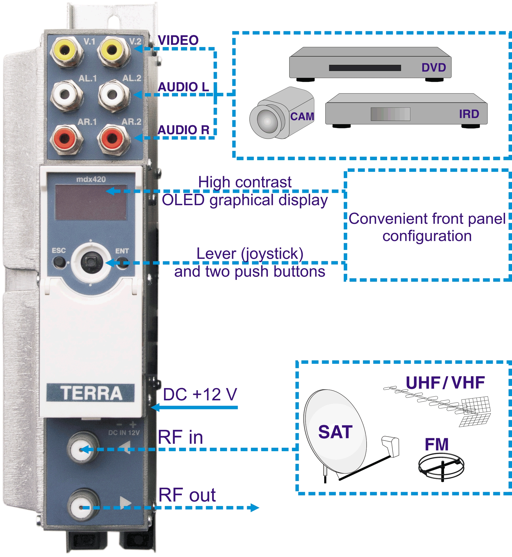
MDX420 – Twin Agile DVB-T TV modulator |
| Modulating analogue video/audio signal into COFDM modulated DVB-T RF channel | |
| – | |
| AV – DVB-T stand-alone modulator | |
| PSI generation: SDT, NIT, LCN | |
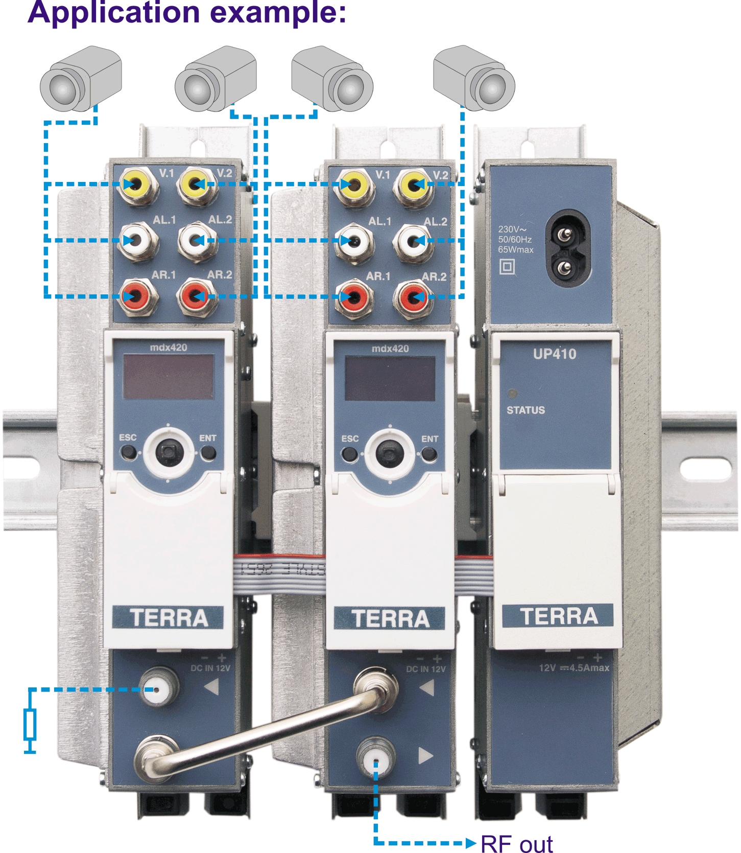
| Processing from 2 video and audio sources into single RF DVB channel | |
| OLED graphical display and joystick control of internal microprocessor | |
| Adjustable RF output level and audio input level | |
| Loop through RF combining | |
| Low level harmonics and intermodulation products | |
| Robust diecast housing | |
| Connectors: | |
| video/audio input – RCA socket | |
| RF – type F | |
| screw terminal block for DC entry power distribution bus | |
| – | |
 |
TV standard: PAL (B, D, G, H, I, M, N, 60); SECAM, NTSC (M, 4.43) |
| Video input: | |
| frequency range 20 Hz – 6 MHz | |
| level/impedance 1 V ± 0.1 V/75 Ω | |
| Audio input: | |
| frequency range 20 Hz – 15 kHz | |
| level/impedance 775 mV/10 kΩ | |
| level adjustment + 6 ÷ -6 dB by 2 dB step | |
| Processing Video: | |
| encoding ISO/IEC13818-2 MPEG-2 MP@ML | |
| resolution 720 x 576 (at 25 fps), 720 x 480 (at 30 fps) | |
| frame rate 25 max. PAL, SECAM, 30 max. NTSC | |
| compressed system bit rate 2…9 Mbps | |
| Processing Audio: | |
 |
encoding ISO /IEC11172-3 (MPEG1 audio) layer 2 compliant |
| sampling rate 44.1 kHz | |
| compressed bit rate 256 Kbps | |
| audio mode Stereo | |
| Modulation: | |
| MER ≥ 35 dB | |
| modulation QPSK, QAM16, QAM64 | |
| channel bandwidth 7/8 MHz | |
| guard interval 1/4, 1/8, 1/16, 1/32 | |
| code rate 1/2, 2/3, 3/4, 5/6, 7/8 | |
| transmission mode 2K | |
| RF output: | |
| frequency range 110 – 860 MHz | |
| level/impedance 85 dBμV/75 Ω | |
| output C/N ≥ 50 dB | |
| output level adjustment range 0 ÷ -15.5 dB by 0.5 dB step | |
| frequency range of RF combining 47-2150 MHz | |
| DC pass through 0.3 A | |
| combining through loss Terr/SAT 1.5/2.5 dB | |
| return loss ≥ 10 dB | |
| Current consumption: 12 V 0.65 A | |
 |
UP410S – Multichannel headend Power supply |
| High efficiency compact power supply | |
| Switch-mode technology | |
| Short circuit and overload protected | |
| DIN rail or wall mounting | |
| Robust diecast housing | |
| Modular power supply with integrated RF combiner | |
| Connectors: | |
| 3xRF – type F | |
| screw terminal block for DC output | |
| – | |
| Power supply: | |
| input voltage 187-250 V~ 50/60 Hz | |
| output voltage, current 12 V 4.5 A max. | |
| power consumption 65 W max. |
|
| – |
|
| Frequency range 47-862 MHz |
|
| Insertion loss 4.5 dB |
|
| Isolation 20 dB | |
| Return loss 16 dB | |
 |
MT420 – Twin Vestigial Analogue TV modulator |
| Modulating analogue video/audio signals into VSB RF channel | |
| VSB modulator, standard B/G/D/K/I/L/Au | |
| – | |
| Two independent frequency agile vestigial sideband TV modulators integrated | |
| into one module | |
| LED display and push buttons control of internal microprocessor | |
| Non-volatile channel memory | |
| PLL crystal stabilization of carriers frequency | |
| Adjustable RF output level and audio input level for every section | |
| Loop through RF combining | |
| Low level harmonics and intermodulation products | |
| Built-in test pattern generator | |
| Robust die-cast housing | |
| Connectors: video/audio input – RCA socket, RF – type F, screw terminal block | |
| for DC entry | |
| – | |
| Frequency range: 110-862 MHz | |
| Video input, frequency range: 20 Hz – 6 MHz | |
| Video input, level/impedance: 1 V ± 0.1 V/75 Ω | |
| Audio input, frequency range: 20 Hz – 15 kHz | |
| Audio input, level/impedance: 775 mV/10 kΩ | |
| Audio input, level adjustment: + 6 ÷ -6 dB by 2 dB step | |
| RF output, level/impedance: 90 dBμV/75 Ω | |
| RF output, level adjustment range: 0 ÷ -10 dB by 1 dB step | |
| RF output, frequency range of RF combining: 47-2150 MHz | |
| RF output, DC pass through: 0.3 A | |
| RF output, combining through loss Terr/SAT: 1.5/2.5 dB | |
| Fine tuning range of video carrier frequency: ± 2.25 MHz max. by 0.25 MHz step | |
| IF bandwidth: 7/8 MHz | |
| S/N ratio, weighted: > 55 dB | |
| A/V ratio: 12/16 dB | |
| IMD2/IMD3 spurious level: < -60 dB | |
 |
AT420 – Twin TV channel amplifier |
| Twin TV channel amplifier tunable in all UHF range | |
| SAW filters provide a high selectivity processing of digital and analog channels | |
| Each section has a built-in AGC system and an independent regulator of output level | |
| Output signal level indication allows to accelerate the search of fault | |
| Digital indication setting of output level | |
| Built-in indicators and push buttons allow operator to set required parameters | |
| DIN rail or wall mounting | |
| Robust die-cast housing | |
| Connectors: 4xRF – type F, screw terminal block for DC entry | |
| – | |
| Tuning range of channels: 470-862 MHz (21-69 ch.) | |
| – | |
| RF input analog, level/impedance: 60-90 dBμV/75 Ω | |
| RF input digital, level/impedance: 45-80 dBμV/75 Ω | |
| RF input, frequency range of RF distribution: 47-862 MHz | |
| – | |
| RF output analog, level/ impedance: 90 dBμV/75 Ω | |
| RF output digital, level/ impedance: 85 dBμV/75 Ω | |
| RF output, frequency range of RF combining: 5-2150 MHz | |
| RF output, DC pass through: 0.3 A | |
| RF output, combining through loss Terr/SAT: 1.5/2.5 dB | |
| RF output, level adjustment range: 0 ÷ -10 dB by 1 dB step | |
| – | |
| AGC dynamic range: 35 dB | |
| Noise figure: 8 dB | |
| Rejection: 45 dB -2 MHz; 45 dB +1.25 MHz from channel border | |
 |
GS15E-3P1J – Power supply |
| High efficiency 12V & 1.25A switch-mode power supply | |
| – | |
| – | |
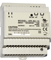 |
DR-60-12 – DIN rail power supply |
| DC output 12V & 4.5A | |
| – | |
| – | |
 |
699.20 – DC distribution cable |
| DC distribution cable for 4 modules | |
 |
|
| Accessories | |
 |
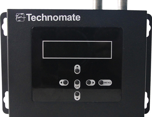
PC100 – Handheld control unit PC100 |
| – | |
| For programming up to 16 modules in 2 subracks of CMH3000, MMH3000 headends | |
| Connection to the data bus through connector, placed on the base unit | |
| 2 line, 16 characters LCD display with back light | |
| – | |
| CMHSW – Control and monitoring software | |
 |
CMH Master – the program is intended for management and diagnostics of the headends |
| CMH3000, MMH3000, RMH3000 | |
| – | |
| PC to the headend is connected through appropriate USB interface | |
| Maximal number of served modules – 256 | |
| Maximal number of served subracks or groups – 16 | |
| Automatic statusing of the headend configuration | |
| User-friendly graphical presentation of all programmable parameters | |
| Obtaining information of the modules status | |
| Fixing of diagnostic information in log-file | |
| Changing headend’s settings in time by composed schedule of events | |
| Possibility to send alarm SMS and remote control of the headend through GSM network by |
|
| PC with GSM terminal | |
| |
|
 |
UD104 – USB-CMH data bus adapter |
| – | |
| RMH3000, CMH3000 and MMH3000 headends PC control supplied with program TERRA Link | |
| – | |
| 11868 | |
| V/A cable (15 Sub-D/3xRCA, length 1.5 m) for external equipment connection to modulators | |
| mt120X | |
| 11876 | |
| 400.025 | |
| 1 module width blank panel for UC180 – Base unit (CMH3000) | |
| – | |
| – | |
| – | |
| – | |
| – | |
can be installed optionally






Leave A Comment
You must be logged in to post a comment.